
A Comparative study of calculation methods and physical results
By Eline R. Norschau, Jørgen S. Jensen, Ken K. L. Lien
Introduction
Most industry is built upon pipes and flanged connections. Every flange poses a risk of leakage, but due to engineering design and safety factors they should not leak when assembled correctly. The development of flange calculations is a much-discussed topic and has come a long way in the last 100 years, yet the methods appear quite conservative resulting in overestimation of flange pressure rating in piping designs.
Early design of piping systems was heavily based on proven design, trial, and error. In 1927 a major shift in the industry takes place with the implementation of ASA B16e, a standardization of existing ASME flanges ready to be used within certain criteria [1].
During the 50’s, the need for a simpler method arises and the Equivalent Pressure Method is developed. The method was popularized through M.W. Kellogg company’s manual “Design of piping systems” in 1956 [2], the method was widely adopted across the field.
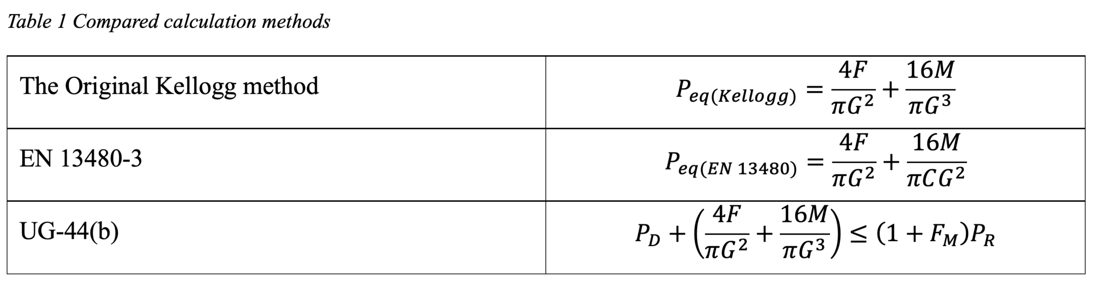
All the methods evaluated and compared in this study have code-specific differences, where the Kellogg method is the origin for both the EN 13480-3 and the ASME BPVC Section VIII Div, and all methods calculate G, gasket reaction diameter, differently [3], [4]. The methods compared are shown in table 1.
The goal of this bachelor thesis is to shed light on the accuracy of flange calculations regarding load limit before leakage. We aim to validate whether the calculation formulas predict the correct leakage load, when compared to physical tests. Furthermore, if the calculation formulas deviate substantially from test result, we want to see if the validity of the formulas can be improved, or a new formula can be adapted.
Method
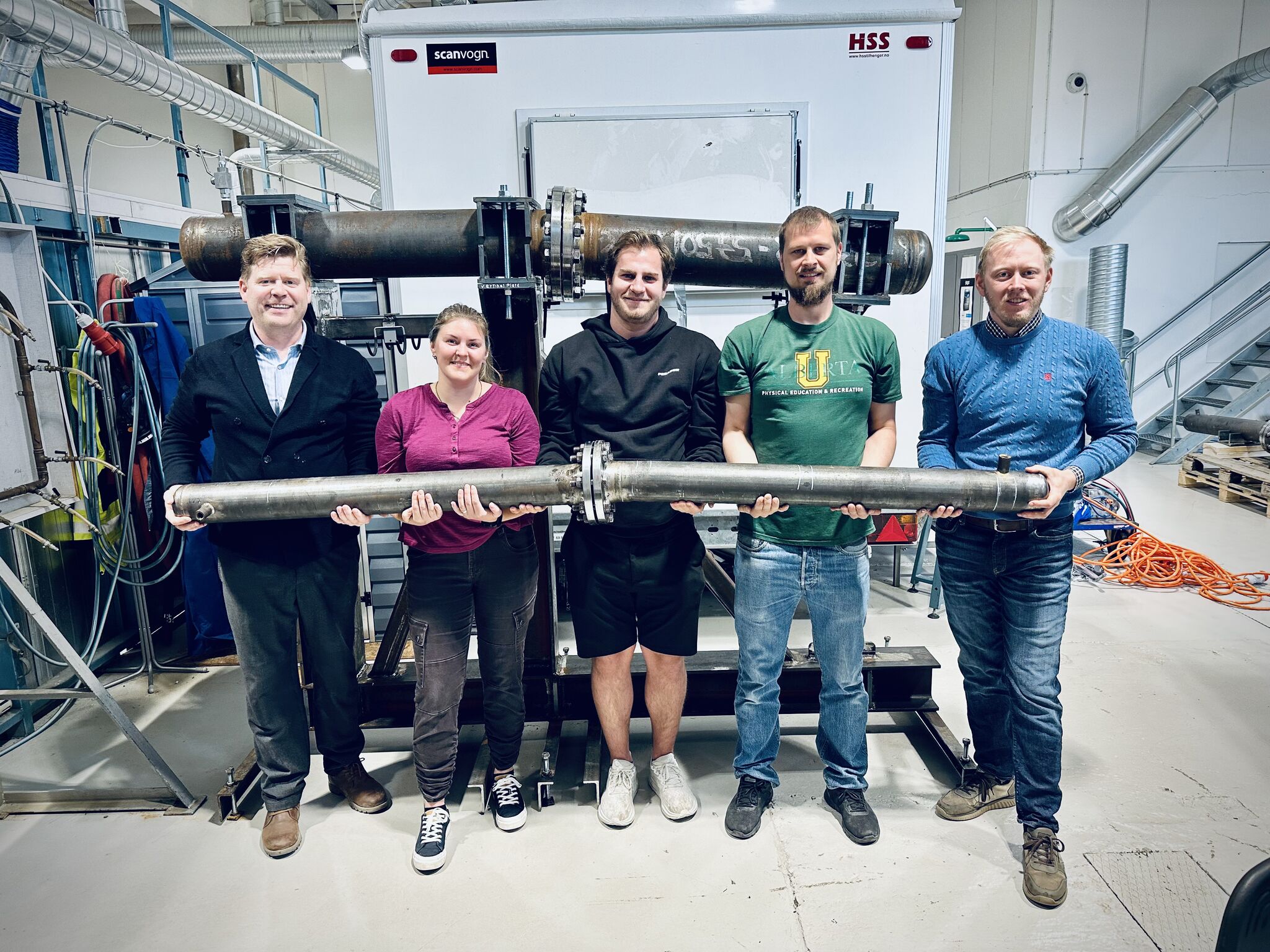
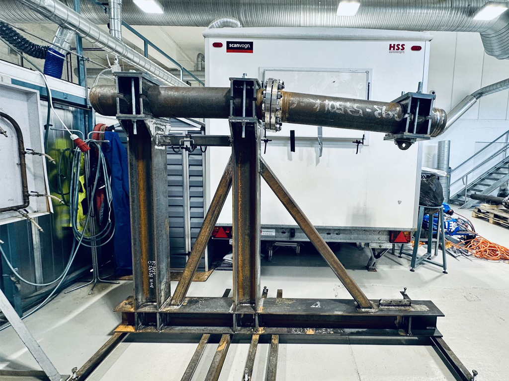
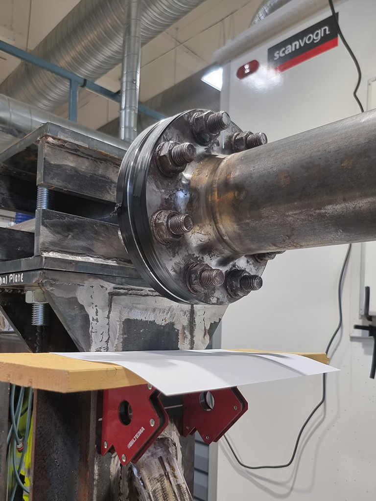
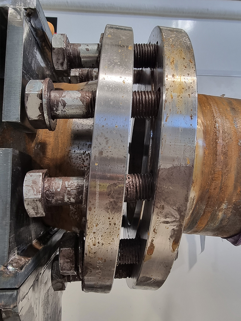
A custom-built test-fixture was constructed specifically for this study. It was dimensioned to withstand a pulling-force of 100kN without any deformation. The pipe-clamps were designed for DN 100, DN 150 and DN 200. The material for the custom cut components was S355J2C, furthermore, the pillars and bottom beam were made from HE180B beam profiles.
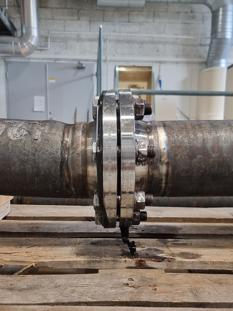
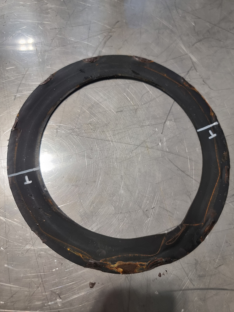
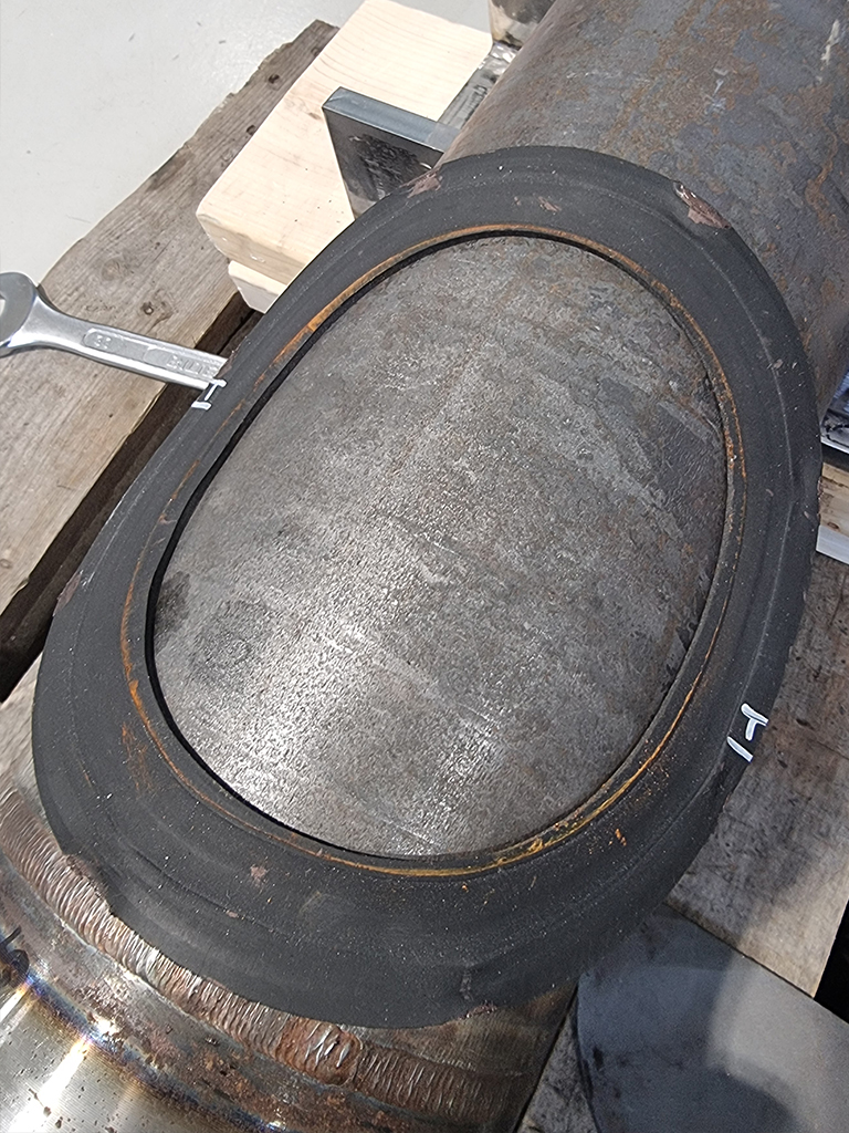
The pipe flanges were assembled using an EPDM EF 51 gasket from Trelleborg, the bolts were torqued in three stages with a maximum bolt torque of 88 Nm, 157 Nm, and 205 Nm for the DN 100, DN 150 and DN 200, respectively. Great effort was put into placing the gasket correctly. Once the pipe was assembled it was lifted onto the fixture and clamped down. The pipe system was then filled with water, air bleed and pressurized to 40 bar using a handpump.
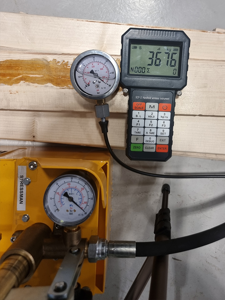
The pulling-cylinders were connected to the front clamp at distance of 1000 mm from the gasket between the flanges. The pipe was pulled downwards until either flange leakage was achieved or the pulling-cylinders bottomed out. The weight applied to the pipe was recorded with a crane scale and the resulting bending moment was calculated.
Results
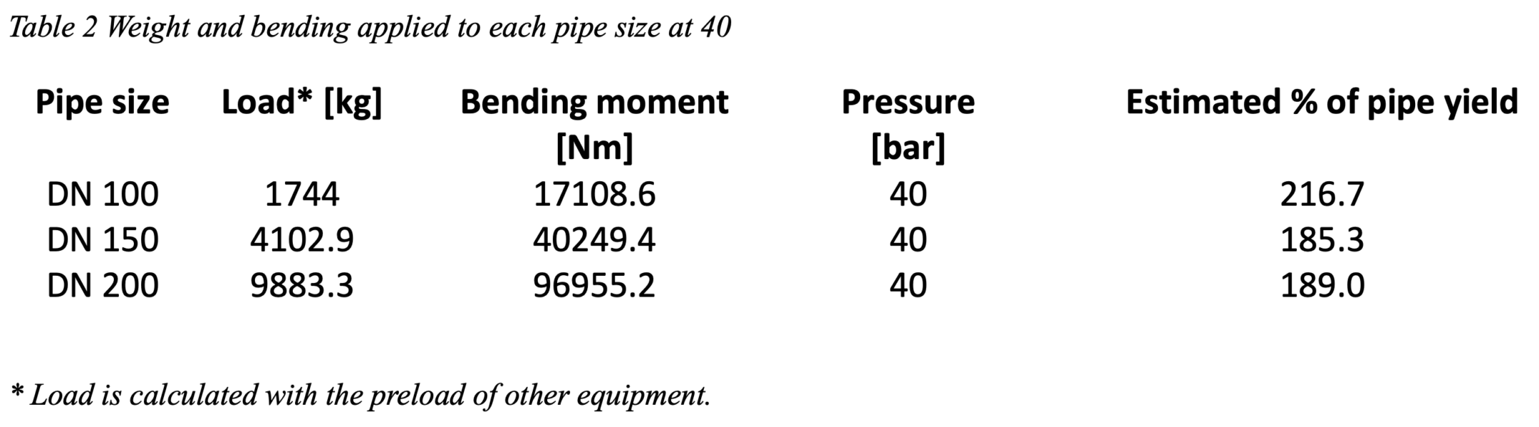
The force applied to the pipes exceeded the material yield strength on all DN sizes, resulting in permanent deformation of the clamped pipe, table 2. Knowing that the pipe stress went above yield, the results regarding estimated percentage of yield should be considered more as a reference to the magnitude of loading than the actual stress.
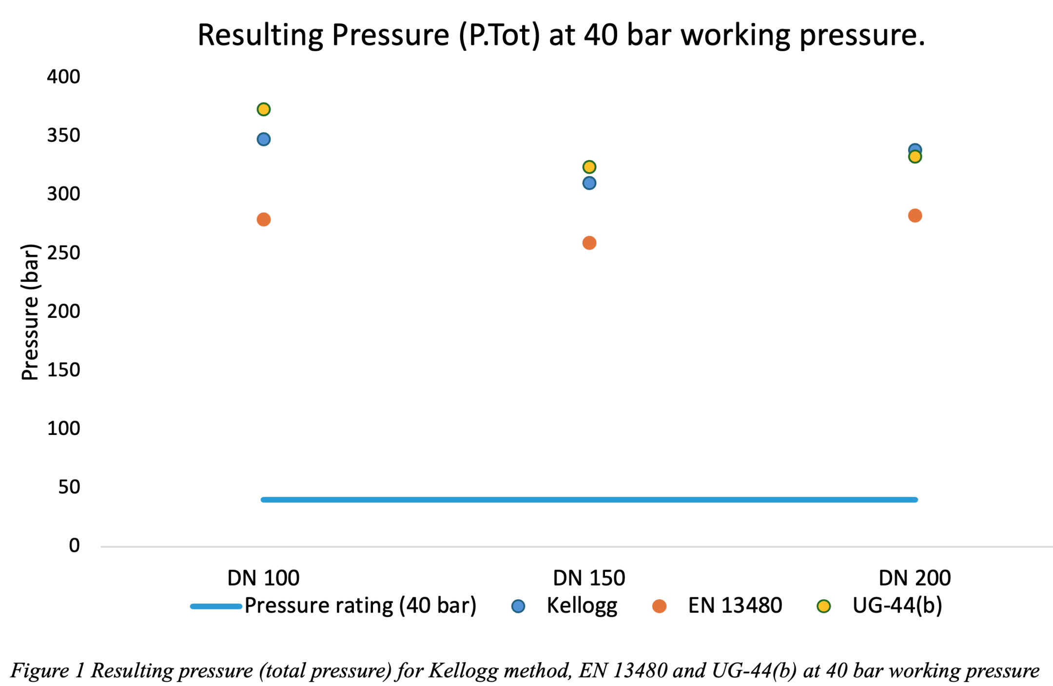
The resulting pressure (P. total) from design pressure and pressure equivalent (Peq), can be seen in figure 1 for 40 bar. The graph shows that for all pipe sizes the EN 13480 method calculated the lowest resulting pressure, with good margin.
For DN 100 and 150 the UG-44(b) calculated the highest pressure, however for the DN 200 the Kellogg method surpassed the UG-44(b) in resulting pressure. The EN 13480 calculated an average of 1.29 ± 0.04 times less pressure than UG-44(b) and 1.25 ± 0.04 times less than Kellogg one all pipe sizes.
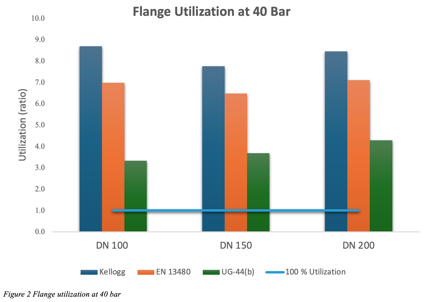
Theoretical flange utilization far surpassed 100% for all calculation methods at 40 bar, see figure 2. Meaning that the resulting pressure far exceeded the theoretical limit of the flanges. The UG-44(b) method deviated significantly less between theoretical flange limit and calculated P. Tot from testing, thus having a lower over-utilization than both the EN 13480-3- and Kellogg- method.
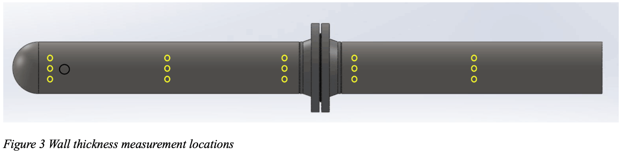
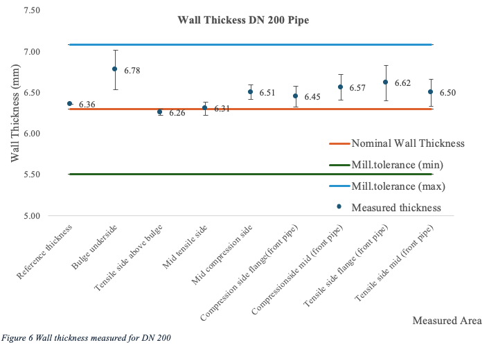
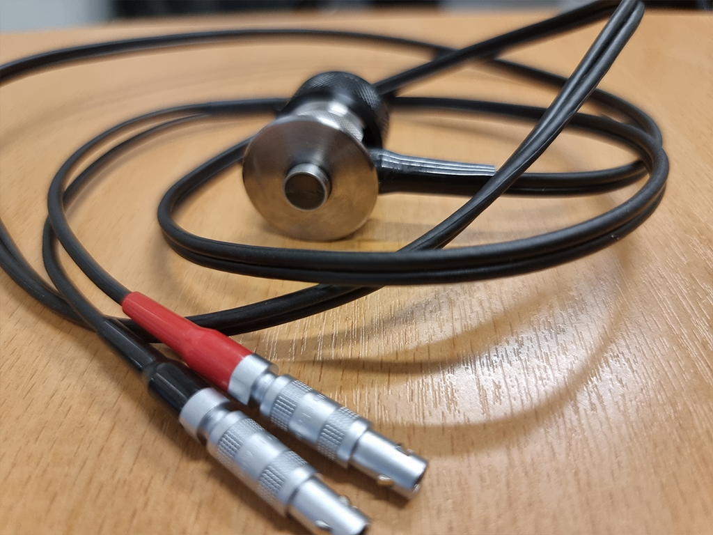
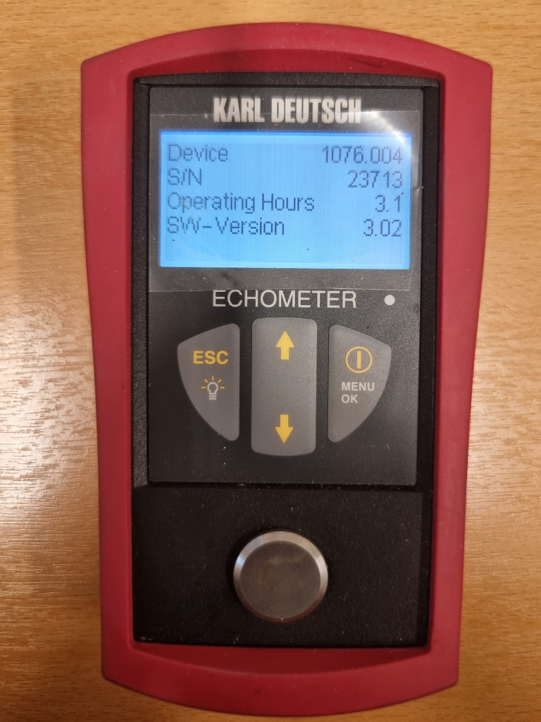
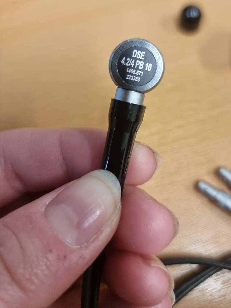
After testing, the wall thickness of the pipes was measured using an ECHOMETER 1076 wall thickness gauge from Karl Dutch, with an accuracy of ±0.1 mm. Three sections of the pipes were of interest, both the tensile- and compressive -side of the pipe were measured, as well as one area for reference thickness. The reference area was chosen as a location where there was no resulting stress from the applied force. The measured areas of interest are shown in figure 3. In total the wall thickness was measured at 9 separate locations including the reference location. Each area had three individual points which were measured approximately 20 mm apart from each other, following the curvature of the pipe.
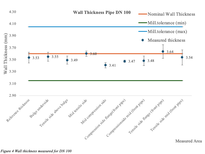
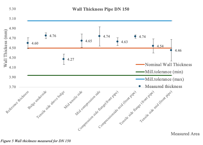
The wall -thickness of the pipes was measured to be well above minimum mill tolerance at all crucial areas after testing, see figure 4, 5 and 6. Apart from a region at the DN 150 pipe (Tensile side above bulge) and the (bulge underside) for DN 200, the difference from reference thickness was negligible for all pipe sizes. Therefore, it could not be established that the testing had reduced the wall thickness in any area.
Gallery
Conclusion
In this research study we were not able to achieve flange leakage regardless of pipe sizes, even though we exceeded estimated leakage pressure as high as 9 times (Kellogg method) and as low as 3.3 times (UG-44(b) method). It is evident that all three methods are very inaccurate when estimating leakage pressure. We also went above yield strength on all pipe sizes without compromising pipe thickness in distressed areas. It is our conclusion that in most cases the pipe would be the weakest link in a pipe system and deform before any flange failure.
Of the three calculation methods the UG-44(b) would be the most accurate when estimating utilization of flange capacity. The EN 13480-3 is more accurate than the Kellogg method, this is because of its use of the bolt circle, C. The UG-44(b) has an advantage over the EN 13480-3 in using the FM factor [5] to adjust the allowable pressure. This is something that would be useful to implement for the EN flange types as well and could significantly increase the threshold for failing a flange joint on wrong premises.
One of the biggest uncertainties is if the pressure equivalent reflects the actual effect of increased static pressure. This question remains unanswered and possibly holds the biggest reward in achieving better calculation methods.
Today’s methods of flange leakage calculations are possibly resulting in more expensive piping systems than necessary because of false flange failure estimations.

References
[1] E. C. Rodabaugh, «Background of ANSI B16.5 Pressure-Temperature Rating». 1972.
[2] M. W. Kellogg, Design of Piping Systems. M. W. Kellogg Company, 1956.
[3] EN 13480 Metallic industrial piping Part 3: Design and calculation, Brussel., 2021 2017.
[4] ASME BPVC VIII Div. 1 Rules for Construction of Pressure Vessels, VIII, USA., 2023.
[5] ASME BPVC.CC.BPV.S4 Code Case 2901-1, Supplement, USA., 2023.