- Does not give consequent results
- Can easily be manipulated without breaking any code rules
- In several cases give confidence to bad mesh and bad results
- Adds 0 value and increase runtime
- Favorites bad engineering by Lower runtime and better results

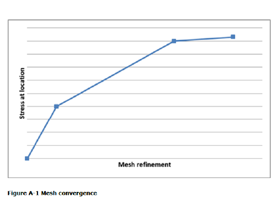
Mesh convergence setup from the code:
Non-linear Analysis:
A mesh convergence is considered reached with a convergence error of 5% on the total strain when a halving of the local element size is applied (ref. DNVGL-RP-F112 Appendix A1.1).
ANSYS Setup:
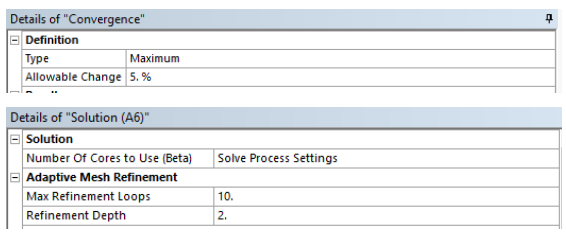
Refinement Depth of 2 equals halving of the element size.
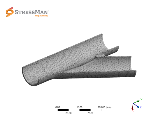
Start Mesh 1
Start Mesh 2
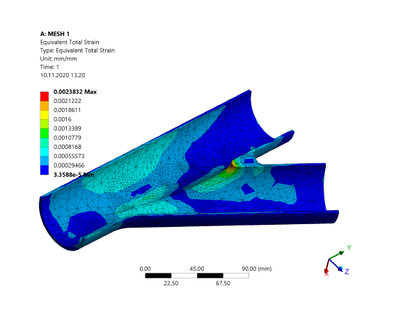
End Mesh 1
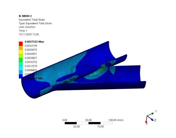
End Mesh 2
Convergence History
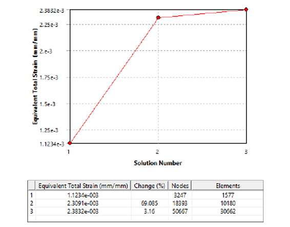
Final strain value 2.3832e-003
Convergence History
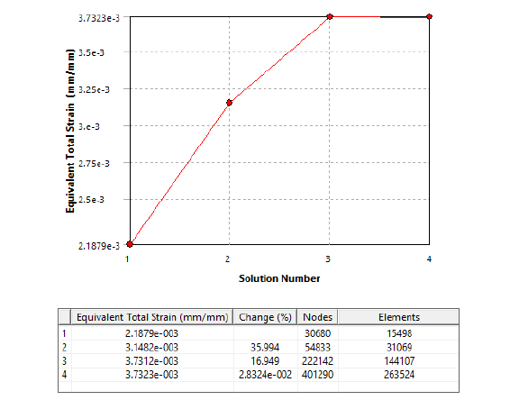
Final strain value 3.7323e-003
57% Calculation error between 1 and 2, but both converged in accordance with DNVGL – RP – F112
What do you do?
•Use common engineering sense
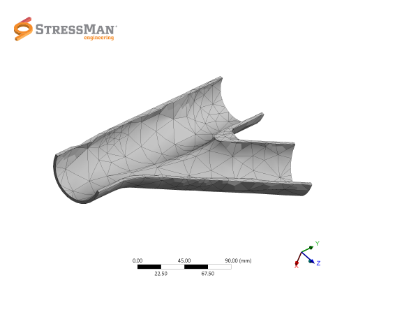
•Ensure that the MESH captures discontinuities
•Run some test and look for a change in results with different MESH
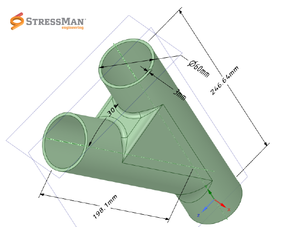
•For piping it is often a good start to have 3 elements across wall thickness and a mesh size of OD X 0.12
Example: This gives a 6” pipe a mesh of 20mm
Example: This gives a 6” pipe a mesh of 20mm
•Be critical when evaluating results